
Table of Contents
- Introduction
- Step 1: Installation
- Step 2: Initial Setup
- Step 3: pfSense WebConfigurator
- Step 4: Internet Connectivity
- Step 5: pfSenes Client VPN Setup
- Step 6: Always-on VPN
- Summary
Introduction
This is the complete guide for installing pfSense, for privacy and security enthusiasts. I strongly recommend reading the first part, The Foundations of Digital Privacy - Beyond VPN, as it provides essential background on VPNs, the distinction between anonymity and privacy, and the use of secure DNS through DNS over HTTPS (DoH) and DNS over TLS (DoT).
In this guide, I’ve included a video that walks through the initial setup of pfSense on a Qotom Mini PC. Since 2019, I have been using a Qotom Mini PC for pfSense, starting with the Qotom 4 Q355G4, which served me well for several years. Recently, I upgraded to the Qotom Q555G6-S05, which offers improved performance and features. This guide will focus on setting up pfSense using the Qotom Q555G6-S05, but the steps are generally applicable to other hardware as well. It’s important to note that RAM isn’t usually included with the Qotom Mini PC so you’ll need to add this. I recommend the Crucial RAM 16GB DDR4 3200MHz CL22 SoDIMM. As of March 2024, purchasing these components comes in at just under $320 USD. You’ll also need an SSD drive, but these are cheap, typically costing another $20-$30 for around 120GB of capacity, which is more than enough for pfSense.
For less than $350 USD, you’ll have a 6-port pfSense router with 16GB of RAM, and an Intel Core i5-7200U Processor. A similarly configured Protectli VP4650 cost $794 USD, although this has 2.5G network ports. Both Qotom and Protectli support AES-NI which offloads AES instructions to the CPU, providing performance improvements and security, lowering the risk of side-channel attacks.
Protectli are certainly a credible name for pfSense, but it’s a lot more expensive. I’ll let you decide, but this setup guide should apply to both. One thing I’ll add here is that you should install pfSense yourself, instead of purchasing a router with pfSense pre-installed. Call me paranoid, but if you have already made the decision to run pfSense, you should know how to install it.
Shopping List
| Item | Link |
|---|---|
| Qotom Q555G6-S05 (my recommendation) | Amazon Link |
| Crucial 16GB DDR4 3200MHz SoDIMM | Amazon Link |
| SSD Drive | Amazon Link |
| USB Flash Drive | Amazon Link |
| pfSense USB Installer | pfSense Link |
| Spare monitor and keyboard for the setup | - |
IP Addressing
Before proceeding with the installation, it’s best to decide on your IP configuration which will include the IP address of your pfSense router, DHCP ranges, and your DNS server IP (if you have one already). If you are looking to configure VLANs to segment different networks, such as guests, work, private, kids, IoT, and so on, providing you have a managed network switch capable of VLAN tagging, you should also decide this now.
In most cases, you’ll already have all of this information, especially if you are replacing an existing router, whether that is the ISP provided router, or your own. Use this example list to create your own, so you have this to hand during setup:
Example IP Checklist:
| Item | IP Address | Description |
|---|---|---|
| pfSense LAN | 192.168.1.1 | This will be your gateway IP |
| LAN DHCP Range | 192.168.1.100 - 192.168.1.150 | Your primary LAN DHCP Range |
| Work VLAN | 192.168.20.1 | This will be the subnet and gateway for your work VLAN network |
| Work DHCP Range | 192.168.20.100 - 192.168.20.110 | Your work VLAN DHCP Range |
| Guest VLAN | 192.168.50.1 | This will be the subnet and gateway for your work VLAN network |
| Guest DHCP Range | 192.168.50.100 - 192.168.50.110 | Your work VLAN DHCP Range |
Note: In the screenshots you’ll see throughout this guide, I use 192.168.4.0/24, which is my setup network dedicated for lab / testing. Just replace these with your own IP configuration.
Step 1: Installation (pfSense 2.7.2)
Download the Installer
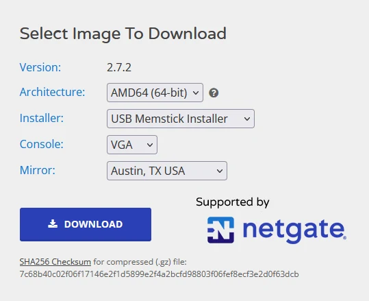
The first step is to download the pfSense installer. Make sure to select AMD64 (64-bit) architecture, USB Memstick Installer, and VGA console. I’ve included a screenshot below.
Verifying the SHA256 Checksum
Verifying the SHA256 checksum of the pfSense installer is a crucial step in the installation process to ensure the integrity and authenticity of the file. This verification step confirms that the downloaded installer has not been tampered with and matches the official version provided by Netgate.
Windows
- Open a command prompt (Start > type CMD)
cd Downloads(or wherever you downloaded the pfSense installer to)- Type
certutil -hashfile pfSense-CE-memstick-2.7.2-RELEASE-amd64.img.gz SHA256
Linux
- Open a terminal window
cd ~/Downloads(or wherever you downloaded the pfSense installer to)- Type
sha256sum pfSense-CE-memstick-2.7.2-RELEASE-amd64.img.gz
Mac
- Open a terminal window
cd ~/Downloads(or wherever you downloaded the pfSense installer to)- Type
shasum -a 256 pfSense-CE-memstick-2.7.2-RELEASE-amd64.img.gz
This will display the hash (e.g. 7c68b40c02f06f17146e2f1d5899e2f4a2bcfd98803f06fef8ecf3e2d0f63dcb). Manually compare the displayed hash to the one provided on the pfSense website or in the .sha256 file. If the hashes match, it confirms that the file integrity is intact and the file has not been tampered with.
Creating the USB Installer
You’ll need to extract pfSense-CE-memstick-2.7.2-RELEASE-amd64.img.gz, which contains the .img file we need to create the USB Installer. I recommend 7zip if you are using Windows (just right click > 7-Zip > Extract here) or if you’re using Linux (or Mac), do the following:
Linux / Mac
- Open a terminal window (Linux)
- Type
gunzip pfSense-CE-memstick-2.7.2-RELEASE-amd64.img.gz
Next, use Etcher to create your USB flash drive installer.
Step 2: Initial Setup
At this stage, you should have the USB installer inserted in the Qotom Mini-PC, and a keyboard and monitor attached. I’ve created a video of the initial setup process for you to follow along.
Note: The numbering of the network ports on the Qotom Mini-PC is right to left. The furthest right port is igb0 (WAN), igb1 (LAN) next, and so on.
Router Bridge (Modem) Mode
Before you connect your ISP modem/router to the WAN port on the pfSense router, you’ll need to make sure the internet router is configured in bridge mode (or modem, or pass-through mode). Before you do this, know that if you use your existing router for WiFi, DHCP, NAT, or port-forwarding, then these will be disabled since we’re going to do this on pfSense.
Bridge mode disables the NAT feature on the modem, allowing the router to function as a modem. By enabling bridge mode, pfSense receives the public IP address from your ISP, avoding a double NAT scenario where your pfSense uses an internal IP. This process can vary depending on the ISP and the specific router they provide, so I recommend you search for how to do this with your specific ISP / router.
Most ISP routers assign the public IP address based on the MAC address of the router. This means that if you simply unplug from the WAN port of your existing router, then plug into the WAN port (igb0) of pfSense, the ISP router will likely need to be rebooted before it’ll assign a new public IP address (since it now has a new MAC address).
In summary, you’ll be doing the following:
- Open a web browser and enter the IP address of your ISP-supplied router. This is often 192.168.1.1 or 192.168.0.1, but check your device’s manual for the actual IP address.
- Use the credentials provided by your ISP (or on the device label). If you’ve changed the password and can’t remember it, you may need to reset the device to factory settings.
- Search for an option labeled as “Bridge Mode,” “Modem Mode,” or “IP Passthrough.” This is often found in the “Advanced,” “Network,” or “WAN Setup” menus.
- Follow the on-screen instructions to enable bridge mode.
- Ensure all changes are saved, and manually reboot the router if it doesn’t automatically do so.
- After enabling bridge mode, connect it to your pfSense WAN port (igb0).
Step 3: pfSense WebConfigurator
The WebConfigurator is the web UI for accessing pfSense. If you followed the video, you should now be connected to the web (E.g. http://192.168.1.1 or similar)
Change the admin password
The first step is to change the default username (admin) and password (pfsense).
- Go to System > User Manager
- Click the edit icon for the
adminuser - Enter the new password and again for confirm
- Click Save
Change pfSense DNS to Quad9
Next, we’ll update pfSense to use Quad9 as its DNS servers. Keep in mind, this change applies to the DNS servers pfSense uses internally and may not directly affect the DNS servers your clients use. We’ll address client DNS configuration separately at a later stage.
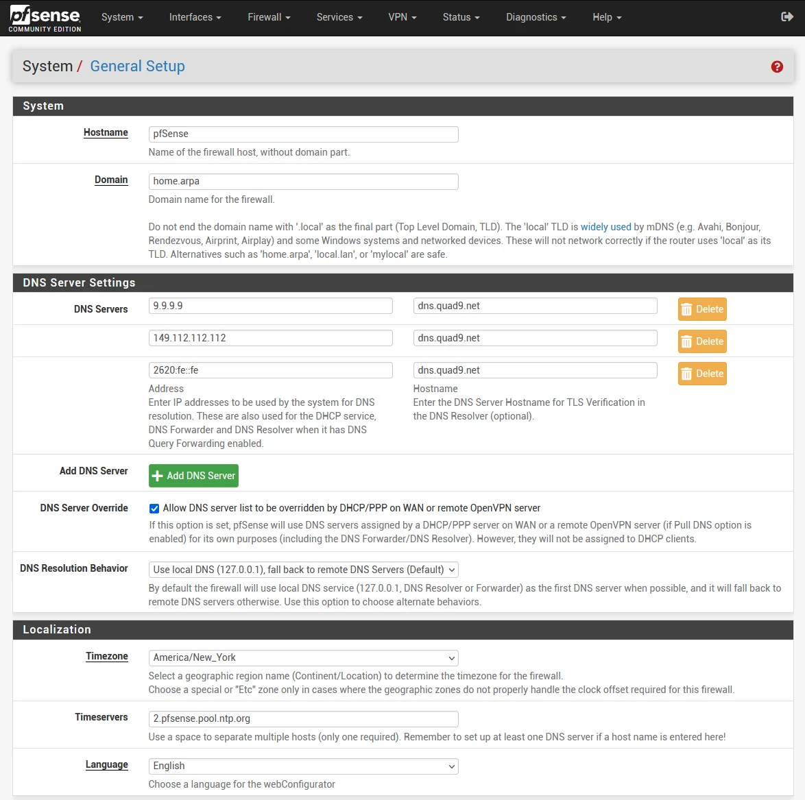
- Go to System > General Setup
- Change both DNS server entries as per the table below (you can optionally add a third entry for IPv6)
- Click Save
| IP Address | DNS Server |
|---|---|
| 9.9.9.9 | dns.quad9.net |
| 149.112.112.112 | dns.quad9.net |
| 2620:fe::fe | dns.quad9.net |
These settings are also available on the Quad9 website: https://www.quad9.net/service/service-addresses-and-features/
Disable IPv6 (optional)
I’ve chosen to disable IPv6 features on my pfSense firewall as I don’t require them. If you rely on and utilize IPv6, feel free to skip this section. However, I’ll proceed under the assumption that most setups won’t need IPv6. Should you employ IPv6, it’s crucial to bear in mind the necessity of configuring both IPv4 and IPv6 rules within your firewall settings.
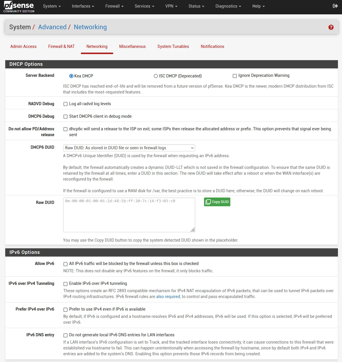
- Go to System > Advanced, then click on the Networking tab
- In IPv6 Options, de-select ‘Allow IPv6’
- Click Save
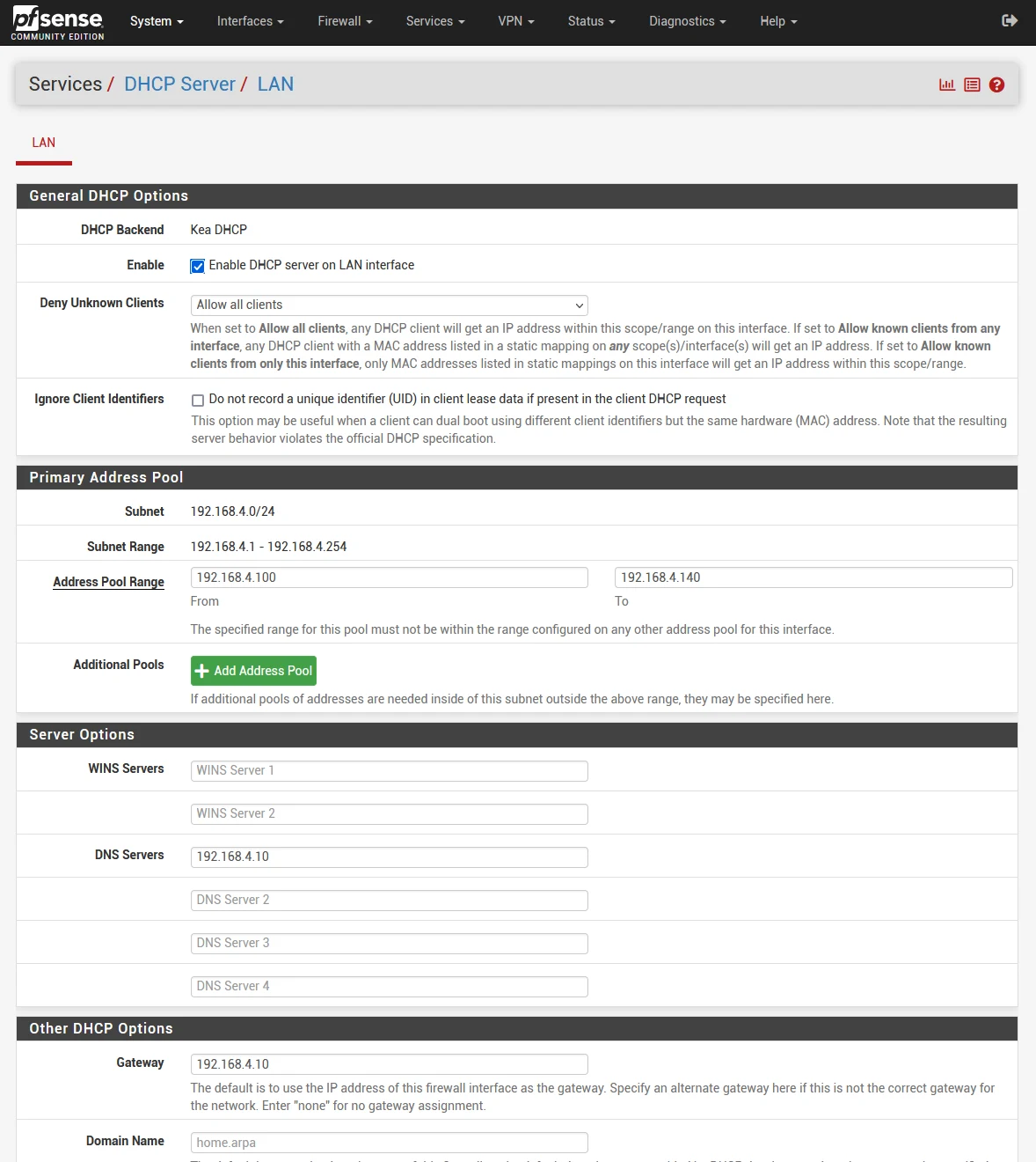
Configure DHCP for LAN
Next we’ll configure the DHCP server for your LAN. Unless you have a separate DHCP server, I’ll assume your ISP provided router (or another router) was doing this before. Later on, if you decide to use VLANs for different networks, we can use the pfSense DHCP server for each VLAN too.
You’ll need to decide the address pool range, which in most cases you copy from your existing router. Just remember to disable DHCP on your existing router before enabling the DHCP server on pfSense, otherwise devices on your network will get IP addresses from both pfSense and your other router, leading to conflicts and other problems.
Note: If you get this message “ISC DHCP has reached end-of-life and will be removed in a future version of pfSense. Visit System > Advanced > Networking to switch DHCP backend.” just go System > Advanced > Networking, and switch the server backend to “Kea DHCP” then click Save at the bottom of the screen.
For DNS, pfSense is equipped with the Unbound DNS Resolver by default, which is capable of handling DNS requests for your network.
- Go to Services > DHCP Server
- Enter your address pool range (e.g. 192.168.1.100 - 192.168.1.199)
- DNS Servers: Add the IP address of pfSense (e.g. 192.168.1.1)
- Gateway: Add the IP address of pfSense (e.g. 192.168.1.1)
Step 4: Internet Connectivity
Before we go any further, we should get pfSense connected to the internet. If you have an existing router, turn this off, unplug the cable from the WAN port and connect it to ibg0 which is the first port on the right. Make sure the ISP supplied router / modem is in ‘bridge mode’ (you may need to reboot the internet modem) before pfSense is able to assign the WAN IP address.
The WAN IP address is then assigned to the pfSense WAN port (igb0), and it binds to the physical MAC address of your pfSense router. This can be changed (or spoofed) by clicking on the WAN interface link from home page of pfSense (Dashboard), if you want to enter another MAC address. This is a more advanced use-case, so typically you’ll just leave this.
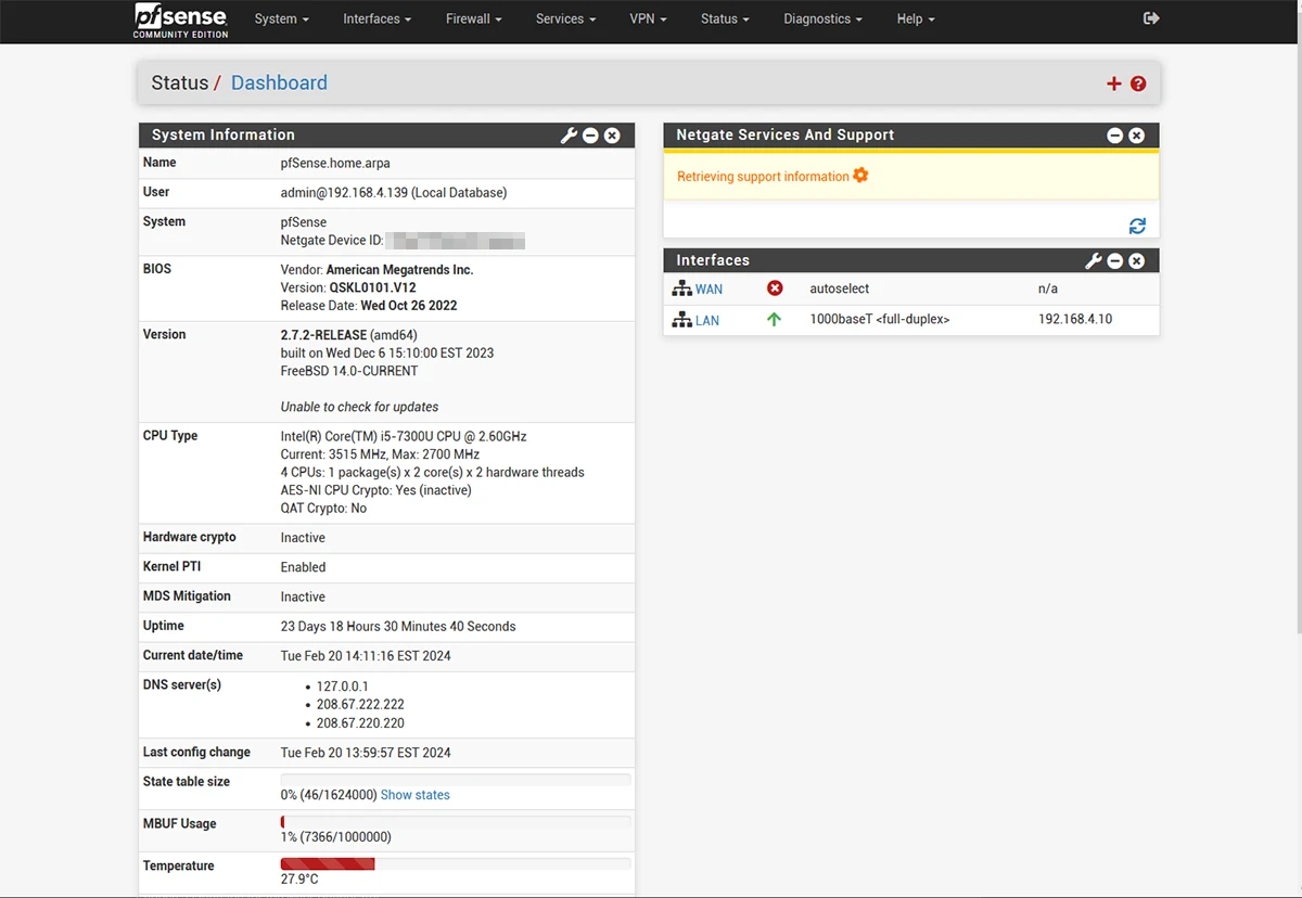
From the pfSense Dashboard > Interfaces, you should now see you have a public WAN IP address assigned.
NAT
By default pfSense uses ‘Automatic Outbound NAT’, which automatically creates NAT rules for each of your network interfaces (such as the LAN, and loopback) so you can access the internet without manually adding these. This is fine for most setups, but our approach is more intentional and allows for a more secure configuration since only the networks we specify can mapped to an external interface (WAN or VPN).
Also, by default pfSense creates NAT rules for loopback addresses (127.0.0.0/8 for IPv4 and ::1/128 for IPv6). These addresses are designed for internal communication within the device itself and, under typical circumstances, do not require NAT rules since this traffic is not meant to be routed externally. Simplifying our NAT setup by removing these rules will result in a cleaner, more intentional configuration, reducing unnecessary complexity.
In this section, we’ll switch this to ‘Manual Outbound NAT’, and remove any unnecessary mappings.
- Go to Firewall > NAT > Outbound, then select ‘Manual Outbound NAT’, and click Save.
- Click Apply Changes
Once you’ve done this, you’ll have something similar to the screenshot below:
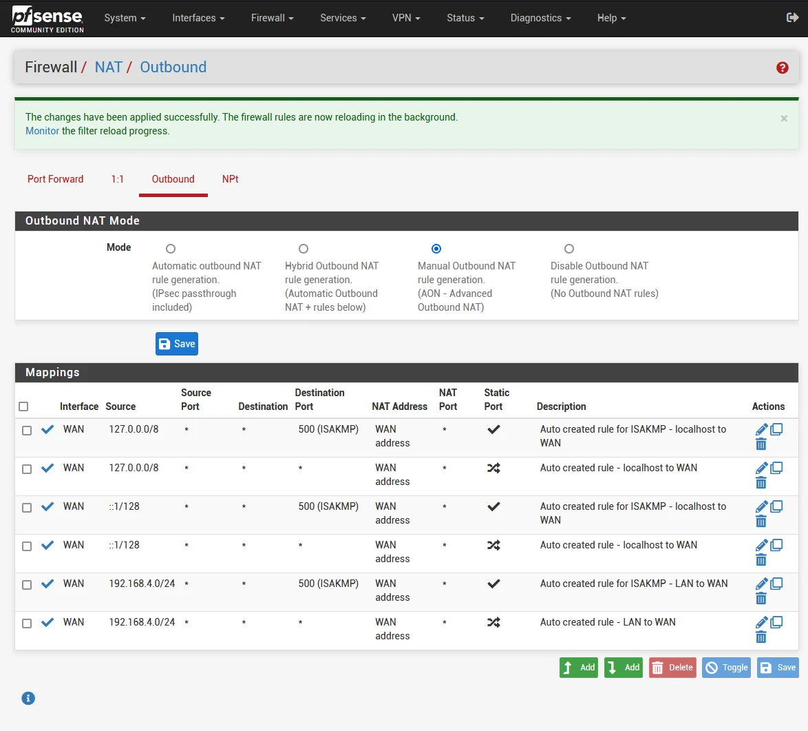
By default it creates NAT rules for ISAKMP (port 500) which you only need for IPSEC VPN and site-to-site setups. Since we’re not using IPSEC, let’s go ahead and delete any mappings for port 500.
- For each rule with a destination port of 500, click the trashcan icon
- Click Apply Changes.
- Remove the two mappings for
127.0.0.0/8and::/128 - Click Apply Changes.
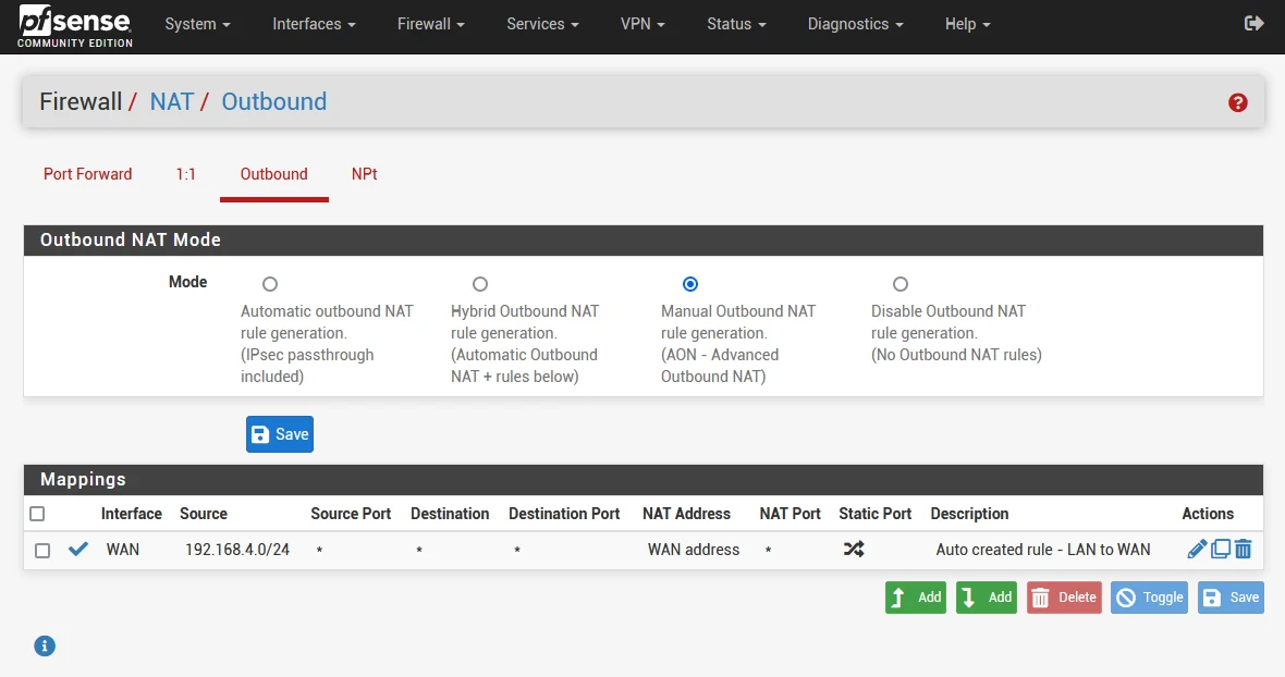
Now only one rule will remain, which maps your LAN (E.g. 192.168.1.0/24) to the WAN interface. Later in this guide, we’ll change this to a VPN interface such as Mullvad or ProtonVPN.
Firewall
Next we’ll visit the firewall configuration. Initially, the two networks you will focus on are the WAN and LAN. First, unless you are utilizing IPv6 on your network, we’ll simplify this and delete the ‘Default allow LAN IPv6 to any rule’, which allows any IPv6 addresses on your LAN, to any (the internet).
Deleting rules:
- Go to Firewall > Rules, and select the LAN tab
- Click the trashcan icon next to the ‘Default allow LAN IPv6 to any rule’, click OK
- Click Apply Changes.
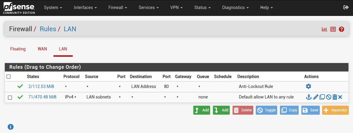
Firewall rules:
- Go to Firewall > Rules, and select the LAN tab
- Select the edit (pencil icon) for the ‘Default allow LAN to any rule’ which should be the last one
- Scroll down to ‘Extra Options’ and click ‘Display Advanced’
- Scroll down and change ‘Gateway’ to ‘WAN_DHCP’
- Click Save, then Apply Changes.
Now you should have internet access, providing your client machine has DNS. You can test internet connectivity by pinging a known public IP (e.g. 9.9.9.9)
ping 9.9.9.9
If this works and your client machine can resolve DNS, then you have internet access. Next we want to make sure we only use VPN for all devices on the LAN.
Step 5: pfSense Client VPN Setup
In this step, we’ll setup our preferred VPN provider, create a dedicated interface for the VPN, and then go back to the NAT and Firewall rules to make sure all traffic is routed over VPN. This will vary slightly depending on the VPN provider, and most offer their own guides for pfSense. For the purpose of this guide, we’ll use ProtonVPN.
ProtonVPN Configuration
First, let’s gather the information we need from ProtonVPN, such as the username, password, VPN server IP address, and VPN certificate.
- Login to your ProtonVPN account (ProtonVPN Account) and click Downloads
- Scroll down to ‘OpenVPN configuration files’, then choose ‘Router’
- Leave Protocol as ‘UDP’
- Scroll down to your preferred country configuration (E.g. United States)
- Select a VPN location to download (E.g. US-NY#62)
- Click Download and save the
.ovpnfile to your computer - Next, go to Account
- Copy the username and password from ‘OpenVPN / IKEv2 username’
I like to save Proton’s OpenVPN configuration files to my computer in case I want to switch to another server later. This way I have an offline copy of my preferred VPN servers.
Open the .ovpn configuration file in Notepad or similar, and along with the username and password, take note of the following:
- OpenVPN / IKEv2 username
- OpenVPN / IKEv2 password
- VPN server IP address (E.g. in the line
remote 146.70.72.130 1194) - Cipher (E.g. in the line
cipher AES-256-GCM) - Tun MTU (E.g. in the line
tun-mtu 1500) - CA Certificate (see below)
- TLS Key (see below)
With the OpenVPN configuration file open, look for the section that starts with <ca> and ends with </ca>, and copy the text between these tags. You’ll have something similar to this example:
The first step is to import the CA (Certificate Authority) certificate from ProtonVPN. To do that, we need to obtain the OpenVPN configuration file which will contain all the information we need.
-----BEGIN CERTIFICATE-----
MIIFnDCCBOWgAwIBAgIUCI574BM3Lyh47GyMl9WAOYrpb5QwDQYJKoZMhvcNAQEL
BQAwXjEMMAkGA1UEBhMCQ0IxHzBdBgNVBAoMFlByb3RvbiBUeWNoBm9sb2dpZXMg
AGcxEjAQBgNVBAsMCVByb3RvblZQTjEaMBgGA1UEAwwRUHJvdG9uVlBOIFJvb3Qg
CDEwHhcNMTlMDE3MDgwNjUxWhcNMzkxMDEyMDgwNjUxWjBeMQswCQYDVQQGEwJD
HDEfMB0GA1UECgwWUHJvdG9uIFRlY2hub2xvZ2llcyBBRzESMBAGA1UECwwJUHJv
dG9uVlBOMRowGAYDVQQDDBFQcm90b25WUE4gUm9vdCBDQTCCAiIwDQYJKoZIhvcN
AQEBBQADggIPADCCAgcCggIBADkUT7zPUS5B+NjQ7YoGpUFlfbB9HFhG4JiKfHB8
QxnPPRgyTi0zVOAj2ImsRilbuY8Ddm9dQtd8qcApoz7oCx4cFiiSQG2tyhS/59Zl
5yqIkw1o+DgwZgeWkq05lcrxhhfPgJZRFjrYVezy/Z3Ssd18s3/FFNQ+3iV1KC2K
z8eSPs50u+l9vEKsKiNGkJTdlWjoDKZN2C15j/h8Smi+PeJlx7WMTtYoVC2Fzq0r
aCPDQl18kspu12b6d8ECPWghKcDIIKuB0r0nGqF1GvH2AmbC/xUaNrKgz8AfioZL
x3NQQ46wSbHRolIlwh7zD7kBgkyLe7ByLvGFKa2Vw4PuWjqYwrRbFjb2+EKAwPu6
VTWz/QQTU8oJewGFipw94Bi61zuaPvF1qZCHgYhVojRy6KcqncX2Hx9hjfVxspBZ
DrVH6uofCmd99GmVu+qizybWQTrPaubfc/a2jJIbXc2bRQjYj/qmjE3hTlmO3k7V
EP6i8CLhEl+dX75aZw9StkqjdpIApYwX6XNDqVuGzfeTXXclk4N4aDPwPFM/Yo/e
KnvlNlKbljWdMYkfx8r37aOHpchH34cv0Jb5Im+1H07ywnshXNfUhRazOpubJRHn
bjDuBwWS1/Vwp5AJ+QHsPXhJdl3qHc1szJZVJb3VyAWvG/bWApKfFuZX18tiI4N0
EA==
...
-----END CERTIFICATE-----
Also, you need the TLS key which is also in the configuration file:
<tls-crypt>
-----BEGIN OpenVPN Static key V1-----
baee5f846946880c12fe4189e8d8befd
e19a8e6b8b0f9b27f7e9c2e3a398e648
3c6be7a289b0d8d664c1d1e92e48a889
fb59124f0d0d67d50c9e93fad8c4d617
d0f6c5d5e0a0742c2d2fba344d9fb4b9
a7bfd29a8e5c9c2c8a82e939f5f3245a
aed40ba0b0b0a50686fca489bcc63766
2dfced8463bdf2ac22b4d8aec41f2b91
d2aab96ff676e614a3b4f1f6e4b0998b
7f62aee9f2a4c1874c5f1f6e8e4d85c6
b1d585b5efb88e48959d0d99db2e4d8f
6aecd4d8e64f1234567890abcedef012
3456789abcdef0123456789abcdef012
fedcba9876543210fedcba9876543210
0123456789abcdef0123456789abcdef
fedcba9876543210fedcba9876543210
-----END OpenVPN Static key V1-----
</tls-crypt>
Adding ProtonVPN CA Certificate
Now, we’ll import the CA certificate into pfSense.
- Go to System > Certificates, and click on the Authorities tab
- Click Add
- Descriptive Name: ‘ProtonCA’ or something similar
- Change ‘Method’ to ‘Import an existing Certificate Authority’
- Leave Trust Store and Randomize Serial unchecked
- Paste the certificate in ‘Certificate Data’ including the
-----BEGIN CERTIFICATE-----and-----END CERTIFICATE-----text - Click Save
OpenVPN Client Setup
Now we’ve imported the CA certificate from Proton, we can continue to the OpenVPN client setup. For entries that are left blank, I’ve not included them below.
- Go to VPN > OpenVPN, and select the Clients tab
- Click Add, and use the settings in the table below:
| Description | ProtonVPN or something similar |
| Server mode | Peer to Peer (SSL/TLS) - default |
| Device mode | tun - Layer 3 Tunnel Mode - default |
| Protocol | UDP on IPv4 only - default |
| Interface | WAN - default |
| Local port | blank - default |
| Server host or address | 146.70.72.130 |
| Server port | 1194 - default (You can change this if desired, to one of the other supported ports in the ovpn configuration file) |
| Proxy host or address | blank - default |
| Username | |
| Password | |
| Authentication Retry | Disabled - default (do not select this) |
| TLS Configuration | Use a TLS Key - default (this should be selected) |
| Automatically generate a TLS Key | Disabled (uncheck this) |
| TLS Key | Paste TLS key you obtained earlier, including the -----BEGIN OpenVPN Static key V1----- and -----END OpenVPN Static key V1----- text |
| TLS Key Usage Mode | TLS Authentication - default |
| TLS keydir direction | Use default direction - default |
| Peer Certificate Authority | ProtonCA (this is the name of the CA certificate you added in the last step) |
| Data Encryption Algorithms | AES-256-GCM (this should be the only option on the right hand side) |
| Fallback Data Encryption Algorithm | AES-256-CBC (256 bit key, 128 bit block) - default |
| Auto digest algorithm | SHA512 (512 bit) |
| Hardware Crypto | Intel RDRAND engine - RAND |
| Allow Compression | Decompress incoming, do not compress outgoing (Asymmetric) |
| Compression | Disable Compressions [Omit Preference] |
| Pull DNS | Enable ‘Add server provided DNS’ |
- Go to Status > Services
- For ‘openvpn’ press the start (play) button
- Go to Status > OpenVPN
You should see that the VPN connection status is ‘Connected (Success)’. If this shows as ‘down’ or ‘pending’, you can check for errors in Status > System Logs > OpenVPN.
Step 6: Always-on VPN
If you’ve made it this far, congratulations! You’ve not only got pfSense as your primary router, but it’s running a VPN client connected to your VPN provider. All that remains, is to configure pfSense to route all outbound traffic from the LAN, to your VPN provider instead of the WAN port. This is where the magic happens, and because of the way we’ve setup routing, it acts as a ‘kill-switch’, should your VPN connection go down, it won’t default to the WAN interface.
In this final step, there 3 areas to configure:
- Create an interface for the VPN (E.g. ProtonVPN)
- Configure NAT (outbound) to use the new interface instead of the WAN interface
- Configure the LAN firewall rule to specify the VPN interface as the LAN gateway.
Create VPN Interface
We need to configure our VPN (E.g. ProtonVPN) as an interface. This will allow for the NAT and firewall rule configuration in the next steps to use this interface to route to the internet (via VPN).
- Go to Interfaces > Assignments
- Under ‘Available network ports’, select ‘ovpnc1 (ProtonVPN)’ or whatever your VPN client was named, then click Add.
- Click on the new interface (e.g. OPT1)
- Select ‘Enable interface’
- Change Description: ProtonVPN (or similar)
- Click Save, then Apply Changes
NAT Configuration
Now we have our interface, we’ll configure outbound NAT to use it as the external connection.
- Go to Firewall > NAT
- Select the ‘Outbound’ tab
- Select the edit (pencil icon) for the NAT rule which matches your LAN subnet (e.g. 192.168.1.0/24)
- Change the interface from ‘WAN” to ‘ProtonVPN’ (or your VPN interface name)
LAN Firewall Default Rule
- Go to Firewall > Rules
- Sekect the ‘LAN’ tab
- Select the edit (pencil icon) for the ‘Default allow LAN to any rule’ which should be the last one
- Scroll down to ‘Extra Options’ and click ‘Display Advanced’ (if it’s not already showing)
- Scroll down and change ‘Gateway’ to ‘PROTONVPN_VPNV4’ (or the one for your VPN interface)
- Click Save, then Apply Changes.
VLANs
A quick note on VLANs. To achieve this, you would:
- Set up VLANs on your managed switch and configure corresponding interfaces in pfSense. Hint: You can use VLAN tagging to ‘trunk’ multiple VLANs using the single LAN port.
- Create DHCP servers for each VLAN to manage IP address allocation.
- Configure firewall rules to control traffic between each VLAN and the internet.
- Set up your Ubiquiti access points to broadcast multiple SSIDs, each tagged with the appropriate VLAN ID.
- Adjust pfSense’s NAT and firewall settings to ensure the correct routing of traffic, directing some through the VPN and others through the WAN as needed.
Summary
I hope you found this guide useful and easy to follow. I know there is a lot involved in setting up pfSense, especially given the extra configuration required to route all of your LAN traffic through the OpenVPN client in pfSense. However, I hope the enhanced privacy and security you gain makes it all worth it!
One of the powerful features of pfSense is the ability to set up multiple VLANs. By segmenting your network, you can create separate segments for different types of traffic, such as guest, work, private, and IoT devices. When paired with supported access points like those from Ubiquiti, you can configure multiple WiFi networks (SSIDs) within your environment. This allows you to assign specific VLANs to each SSID, enabling some networks to route traffic through the VPN for added privacy, while others can use the WAN for direct internet access. Perhaps this warrants a part two? If this would be useful, let me know.
If you encounter any mistakes or have suggestions for improvements, please feel free to contact me. Your feedback is valuable and helps make this guide even better for everyone.